Create Pipeline
Plant Engineering > New > Create pipeline 
Select this function to create a new pipeline. The Create pipeline dialogue window will be displayed.
|
Name |
Use this function to specify a name for the pipeline. The name suggested by HiCAD is PIPELINE_, followed by the lowest possible number which has not yet been assigned in the current drawing. If you select another number, the system will check whether this number has already been assigned. If this is the case, an appropriate message will be issued. Instead of the name suggested by HiCAD you may also select an arbitrary name. When you create a pipeline, HiCAD automatically create two parts in the active drawing: a main part PIPELINE_nnnn and a sub-part ~Parts. |
|
As sub-part |
New pipelines can be directly created as sub-parts to the active part. For example, if you want the new pipeline to belong to an assembly, call the Create pipeline function and activate the as sub-part checkbox. |
|
BOM-relevant |
New pipelines can be marked as BOM-relevant directly during their creation by activating this checkbox. |
|
|
Colour of the pipeline. |
|
|
Layer assigned to the pipeline. |
|
Assign pipe class |
You can assign a Pipe class and a Nominal diameter to the pipeline. This specification ensures that you can only insert parts fulfilling the criteria determined by the pipe class and nominal diameter in the pipeline. If you want to assign a pipe class, activate the Pipe class from P+ID
or
If you click the Select P+ID symbol, HiCAD automatically switches to the appropriate P+ID. You can now use the cursor to select the pipeline symbol (represented by the graphic text of its alias). You can display the appropriate data mask and the data of the assigned pipe class. When you select the symbol you are automatically returned to the layout plan and the dialogue box described herein. If you have assigned a nominal diameter to the P+ID symbol, it will be displayed as well and applied to the pipeline to be created. If no nominal diameter has been assigned to the P+ID symbol, this will also apply to the pipeline to be created. If no pipe class, but only a nominal diameter has been assigned to the P+ID symbol, the checkbox is switched automatically and the nominal diameter will be displayed under Assign nominal diameter. The name of the pipeline will also be adapted from the P+ID.
Pipe class from database
Pipe class from file list
Pipe class from reference part
|
|
Assign nominal diameter |
If you want to assign a nominal diameter, please note the following:
If you do not want to assign a pipe class, but a nominal diameter, deactivate the Assign pipe class checkbox You have now the following options to specify the nominal diameter to be assigned: Nominal diameter from reference part
Nominal diameter via direct specification
|
|
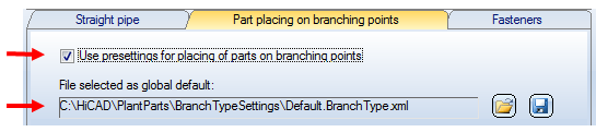
Use this function to assign specifications concerning the placing of parts on branching points. This takes place via the name of the file containing the corresponding definitions. Click the
If a file has been assigned, the definitions in this file, and not those ones belonging to the file that is set as the global presetting in the Plant Engineering Settings. But the definitions in the assigned file, too, will only be used if the Use presettings for placing of parts on branching points checkbox has been activated.
The name of this assigned file will be saved, together with the other properties of the pipeline, when saving a configuration. If a pipe class has been assigned to the pipeline as well, the standard designations that may have been specified in the definitions will be ignored. |
|
|
In the lower part of the dialogue window you have the option to load and save pipeline configurations.
A pipeline configuration (file format .XML) comprises the following settings displayed in the dialogue:
Select the desired configuration from the list box. This can be the default configuration, the last used configuration, or any other configuration file that you have created. |


 Assign pipe class checkbox. You can now choose between three options:
 and activate the
  symbol to edit the definitions for the file.

When you have specified the identification number, the pipe class and nominal diameter for the pipeline, click OK. Use the Guideline Tools functions to specify the routeof the pipeline.
If you exit the dialogue box with Cancel, HiCAD ignores all entries and does not create a new pipeline.
 If you have selected the HiCAD Catalogue (and not the HELiOS Database) as part data source (see Plant Engineering Settings), no pipe class management is available, and the assigning of pipe classes to pipelines will not be possible.


Select Pipeline (PE) • Pipeline Tools (PE) • Plant Engineering Functions